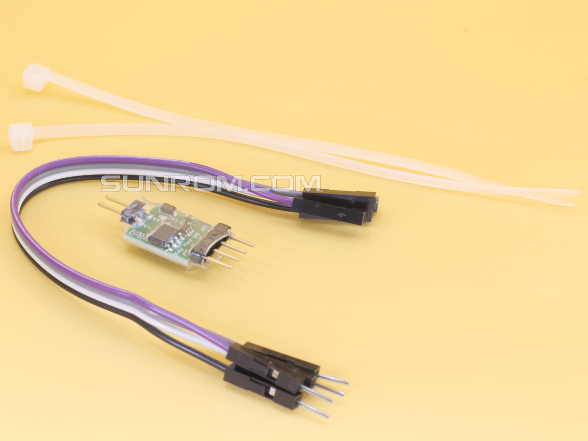
Auto-Power-On Module for Desktop PCs and Servers
Useful where server is remote and unattended and needs to be constant powered on after a power loss.

Auto-Power-On Module for Desktop PCs and Servers
Sunrom Product Code for Ordering:
8109
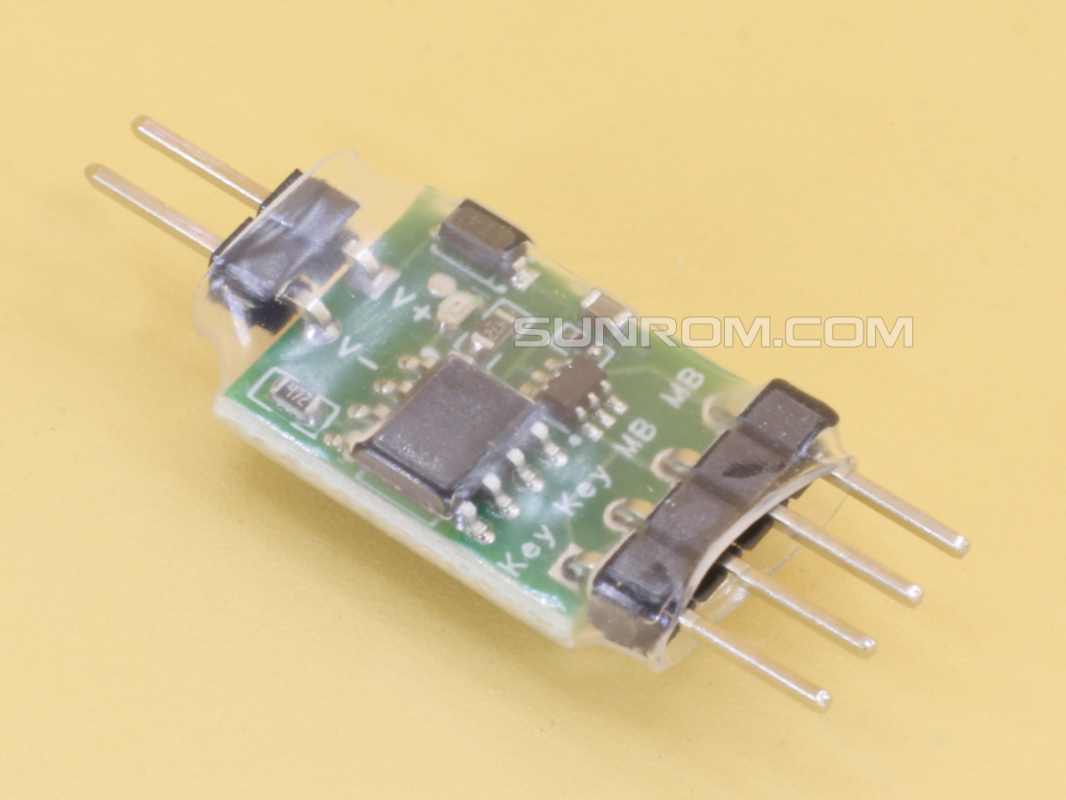
This device is an **Auto-Power-On Module** for desktop computers. Its purpose is to automatically "press" the power button about 2 seconds after the computer receives electricity (useful for servers or PCs that need to restart automatically after a power outage).
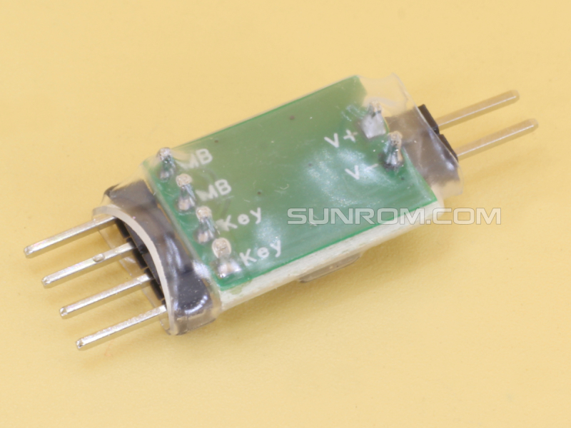
## Pin Layout & Wiring Guide
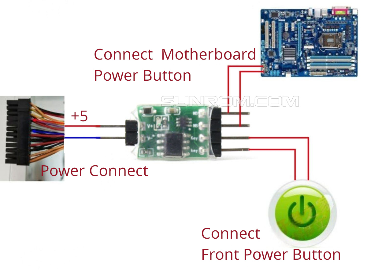
The module acts as a "bridge" between your motherboard's power headers and your case's physical power button.
### 1. Power Input (Left Side V+ V-)
These two wires provide standby power to the module so it can work even when the PC is off.
* **Positive (+) / Purple Wire:** Connect to the **+5V Standby (5VSB)** line on your 24-pin ATX power cable.
* **Negative (-) / Black Wire:** Connect to any **Ground (GND)** line on the 24-pin ATX cable.
> **Note:** The blue LED on the module will light up once it is receiving power correctly.
### 2. Output to Motherboard (Top Right - Pins 1 & 2 MB)
These pins connect to the **Front Panel Header** on your motherboard.
* **Location:** Look for the pins labeled `PWR_SW`, `PW`, or `Power Switch`.
* **Connection:** These two pins should be plugged into the motherboard where your case's power button used to go.
### 3. Input from Case Button (Bottom Right - Pins 3 & 4 KEY)
This allows your physical case button to still function normally.
* **Connection:** Plug the two-pin cable coming from your **PC Case Power Button** into these pins.
## Instructions
**Module Specifications:**
* **Size:** 32mm x 12mm
* **Power Supply:** DC 3.3V - 5V
**How to Use:**
1. **Locate Power:** Unplug the 24-pin main power cable from your motherboard. Identify the **Purple** wire (+5V) and any **Black** wire (Ground).
2. **Insert Pins:** Insert the module's power input leads into the back of the 24-pin connector (Purple to Positive, Black to Negative).
3. **Secure:** Use a zip tie to secure the wires so they don't slip out.
4. **Connect Headers:** * Connect the "Motherboard" side of the module to the `PWR_SW` pins on the motherboard.
* Connect your case's "Power Button" cable to the "Key" pins on the module.
5. **Reassemble:** Plug the 24-pin cable back into the motherboard.
---