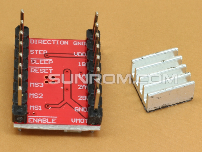
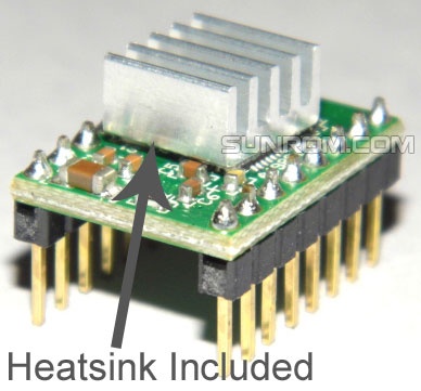
Stepper Motor Driver Module A4988 + Heatsink
Microstepping bipolar stepper motor driver based on Allegro’s A4988 for 8-35V at 2A max operation.


Downloads
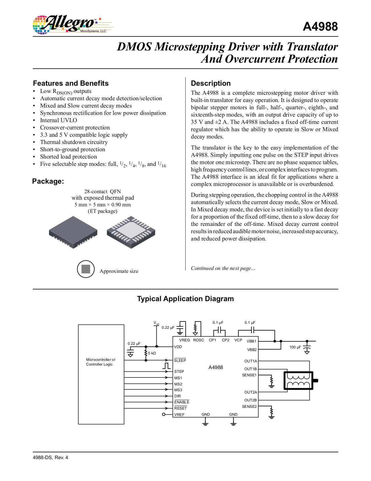
A4988 DatasheetBased on Allegro’s A4988 microstepping bipolar stepper motor driver. The driver features adjustable current limiting, overcurrent and overtemperature protection, and five different microstep resolutions (down to 1/16-step). It operates from 8 – 35 V and can deliver up to approximately 1 A per phase without a heat sink or forced air flow (it is rated for 2 A per coil with sufficient additional cooling).
We recommend careful reading of the A4988 datasheet(righ side of this page) before using this product. This stepper motor driver lets you control one bipolar stepper motor at up to 2 A output current per coil.
Features
- Simple step and direction control interface
- Five different step resolutions: full-step, half-step, quarter-step, eighth-step, and sixteenth-step
- Adjustable current control lets you set the maximum current output with a potentiometer, which lets you use voltages above your stepper motor’s rated voltage to achieve higher step rates
- Intelligent chopping control that automatically selects the correct current decay mode (fast decay or slow decay)
- Over-temperature thermal shutdown, under-voltage lockout, and crossover-current protection
- Short-to-ground and shorted-load protection
This product ships with all surface-mount components including the A4988 driver IC installed as shown in the product picture below.
Using the Driver
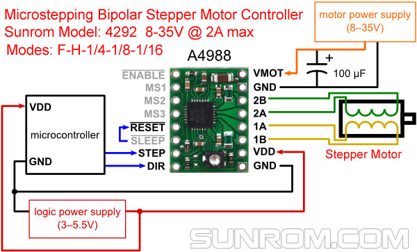
Minimal wiring diagram for connecting a microcontroller to an A4988 stepper motor driver carrier (full-step mode).
Power connections
The driver requires a logic supply voltage (3 – 5.5 V) to be connected across the VDD and GND pins and a motor supply voltage (8 – 35 V) to be connected across VMOT and GND. These supplies should have appropriate decoupling capacitors close to the board, and they should be capable of delivering the expected currents (peaks up to 4 A for the motor supply).
Warning: This carrier board uses low-ESR ceramic capacitors, which makes it susceptible to destructive LC voltage spikes, especially when using power leads longer than a few inches. Under the right conditions, these spikes can exceed the 35 V maximum voltage rating for the A4988 and permanently damage the board, even when the motor supply voltage is as low as 12 V. One way to protect the driver from such spikes is to put a large (at least 47 µF) electrolytic capacitor across motor power (VMOT) and ground somewhere close to the board.
About Stepper Motors
Stepper motor drivers are brushless DC motor drivers that can be used for both positioning and velocity control applications without the need for external position feedback. Typical stepper motors consist of a rotating permanent magnet (rotor) surrounded by electromagnets (stator). When the electromagnets are supplied current in the correct polarity and sequence a torque is created that moves the rotor in steps. These steps can be sequenced together to move the rotor at various speeds corresponding to the sequence rate. Positioning can be accomplished by controlling the number of sequenced steps.
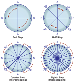
By precisely controlling the current in each motor phase you can divide a motor’s fundamental step angle into smaller microsteps. Microstepping results in better positional resolution, less resonance issues and lower audible noise
Motor connections
Four, six, and eight-wire stepper motors can be driven by the A4988 if they are properly connected;
When working with stepper motors, you will typically encounter two types: unipolar stepper motors and bipolar stepper motors. Unipolar motors have two windings per phase, allowing the magnetic field to be reversed without having to reverse the direction of current in a coil, which makes unipolar motors easier to control than bipolar stepper motors. The drawback is that only half of the phase is carrying current at any given time, which decreases the torque you can get out of the stepper motor. However, if you have the appropriate control circuitry, you can increase the stepper motor torque by using the unipolar stepper motor as a bipolar stepper motor (note: this is only possible with 6- or 8-lead unipolar stepper motors, not with 5-lead unipolar stepper motors). Unipolar stepper motors typically have five, six, or eight leads.
Bipolar steppers have a single coil per phase and require more complicated control circuitry (typically an H-bridge for each phase). The A4988 have the circuitry necessary to control a bipolar stepper motor. Bipolar stepper motors typically have four leads, two for each coil.
Four Lead Motors
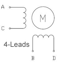
The above diagram shows a standard bipolar stepper motor. To control this with the A4988, connect stepper lead A to board output 1A, stepper lead C to board output 1B, stepper lead B to board output 2A, and stepper lead D to board output 2B. See the A4988 datasheet for more information.
Six Lead Motors
If you have a six-lead unipolar stepper motor as shown in the diagram below, you can connect it to the A4988 as a bipolar stepper motor by making the bipolar connections described in the section above and leaving stepper leads A’ and B’ disconnected. These leads are center taps to the two coils and are not used for bipolar operation.

Eight Lead Motors
If you have an eight-lead unipolar stepper motor as shown in the diagram below;
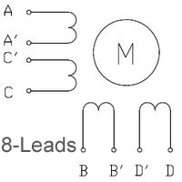
you have several connection options. An eight-lead unipolar stepper motor has two coils per phase, and it gives you access to all of the coil leads (in a six-lead unipolar motor, lead A’ is internally connected to C’ and lead B’ is internally connected to D’). When operating this as a bipolar stepper, you have the option of using the two coils for each phase in parallel or in series. When using them in parallel, you decrease coil inductance, which can lead to increased performance if you have the ability to deliver more current. However, since the A4988 actively limit the output current per phase, you will only get half the phase current flowing through each of the two parallel coils. When using them in series, it’s like having a single coil per phase (like in four-lead bipolar steppers or six-lead unipolar steppers used as bipolar steppers). We recommend you use a series connection.
To connect the phase coils in parallel, connect stepper leads A and C’ to board output 1A, stepper leads A’ and C to board output1B, stepper leads B and D’ to board output 2A, and stepper leads B’ and D to board output 2B.
To connect the phase coils in series, connect stepper lead A’ to C’ and stepper lead B’ to D’. Stepper leads A, C, B, and D should be connected to the stepper motor driver as normal for a bipolar stepper motor (see the bipolar stepper connections above).
Warning: Connecting or disconnecting a stepper motor while the driver is powered can destroy the driver. (More generally, rewiring anything while it is powered is asking for trouble.)
Step (and microstep) size
Stepper motors typically have a step size specification (e.g. 1.8° or 200 steps per revolution), which applies to full steps. A microstepping driver such as the A4988 allows higher resolutions by allowing intermediate step locations, which are achieved by energizing the coils with intermediate current levels. For instance, driving a motor in quarter-step mode will give the 200-step-per-revolution motor 800 microsteps per revolution by using four different current levels.
The resolution (step size) selector inputs (MS1, MS2, and MS3) enable selection from the five step resolutions according to the table below. MS1 and MS3 have internal 100kΩ pull-down resistors and MS2 has an internal 50kΩ pull-down resistor, so leaving these three microstep selection pins disconnected results in full-step mode. For the microstep modes to function correctly, the current limit must be set low enough (see below) so that current limiting gets engaged. Otherwise, the intermediate current levels will not be correctly maintained, and the motor will skip microsteps.
| MS1 | MS2 | MS3 | Microstep Resolution |
|---|---|---|---|
| Low | Low | Low | Full step |
| High | Low | Low | Half step |
| Low | High | Low | Quarter step |
| High | High | Low | Eighth step |
| High | High | High | Sixteenth step |
Control inputs
Each pulse to the STEP input corresponds to one microstep of the stepper motor in the direction selected by the DIR pin. Note that the STEP and DIR pins are not pulled to any particular voltage internally, so you should not leave either of these pins floating in your application. If you just want rotation in a single direction, you can tie DIR directly to VCC or GND. The chip has three different inputs for controlling its many power states: RST, SLP, and EN. For details about these power states, see the datasheet. Please note that the RST pin is floating; if you are not using the pin, you can connect it to the adjacent SLP pin on the PCB to bring it high and enable the board.
Current limiting
To achieve high step rates, the motor supply is typically much higher than would be permissible without active current limiting. For instance, a typical stepper motor might have a maximum current rating of 1 A with a 5Ω coil resistance, which would indicate a maximum motor supply of 5 V. Using such a motor with 12 V would allow higher step rates, but the current must actively be limited to under 1 A to prevent damage to the motor.
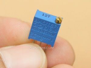
The A4988 supports such active current limiting, and the trimmer potentiometer on the board can be used to set the current limit. One way to set the current limit is to put the driver into full-step mode and to measure the current running through a single motor coil without clocking the STEP input. The measured current will be 0.7 times the current limit (since both coils are always on and limited to 70% of the current limit setting in full-step mode). Please note that changing the logic voltage, Vdd, to a different value will change the current limit setting since the voltage on the “ref” pin is a function of Vdd.
Another way to set the current limit is to measure the voltage on the “ref” pin and to calculate the resulting current limit (the current sense resistors are 0.05Ω). The ref pin voltage is accessible on a via that is circled on the bottom silkscreen of the circuit board. The current limit relates to the reference voltage as follows:
Current Limit = VREF × 2.5
So, for example, if the reference voltage is 0.3 V, the current limit is 0.75 A. As mentioned above, in full step mode, the current through the coils is limited to 70% of the current limit, so to get a full-step coil current of 1 A, the current limit should be 1 A/0.7=1.4 A, which corresponds to a VREF of 1.4 A/2.5=0.56 V. See the A4988 datasheet for more information.
Note: The coil current can be very different from the power supply current, so you should not use the current measured at the power supply to set the current limit. The appropriate place to put your current meter is in series with one of your stepper motor coils.
Power dissipation considerations
The A4988 driver IC has a maximum current rating of 2 A per coil, but the actual current you can deliver depends on how well you can keep the IC cool. The carrier’s printed circuit board is designed to draw heat out of the IC, but to supply more than approximately 1 A per coil, a heat sink or other cooling method is required.
This product can get hot enough to burn you long before the chip overheats. Take care when handling this product and other components connected to it.
Please note that measuring the current draw at the power supply will generally not provide an accurate measure of the coil current. Since the input voltage to the driver can be significantly higher than the coil voltage, the measured current on the power supply can be quite a bit lower than the coil current (the driver and coil basically act like a switching step-down power supply). Also, if the supply voltage is very high compared to what the motor needs to achieve the set current, the duty cycle will be very low, which also leads to significant differences between average and RMS currents.