TFT LCD 40x2 Sunrom's Standard Interface
Pinout details
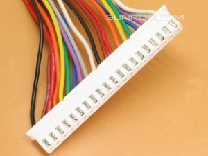
Sunrom's Standard 40 pin(20x2) TFT LCD Interface


| Pin# | Pin Name | Details |
|---|---|---|
| 1 | GND | Power Ground |
| 2 | VCC | Positive Power Input, Regulated +3.3V supply required |
| 3 | NC | Not Connected |
| 4 | RS | Data / Command selection |
| 5 | WR | Signal to Write data on Data bus |
| 6 | RD | Signal to Read data on Data bus |
| 7-14 | DB8-DB15 | Upper 8 bit Data bus (Voltage Level max 3.3V) |
| 15 | CS | Chip Select |
| 16 | NC | Not Connected |
| 17 | REST | Reset (during the reset operation: Pull low for 8ms; then pull high for normal operation) |
| 18 | NC | Not Connected |
| 19 | LED_A | +3.3V Backlight positive power supply input (LCD has built in 3.9 Ohm resistor in series to limit current to backlight, Do NOT give 5V to this pin.) |
| 20 | NC | Not Connected |
| 21-28 | DB0-DB7 | Lower 8 bit Data bus (Voltage Level max 3.3V) |
| 29 | T_CLK | Touch controller (XPT2046) clock |
| 30 | T_CS | Touch controller (XPT2046) Chip Select |
| 31 | T_DIN | Touch controller (XPT2046) data in (MOSI) |
| 32 | NC | Not Connected |
| 33 | T_DO | Touch controller (XPT2046) data out (MISO) |
| 34 | T_IRQ | Touch controller (XPT2046) data interrupt (usually high, goes low when screen is touched) |
| 35 | SD_DO | SD Card data output(MISO) |
| 36 | SD_CLK | SD Card clock (SCK) |
| 37 | SD_DIN | SD Card data in (MOSI) |
| 38 | SD_CS | SD Card chip select |
| 39 | NC | Not Connected |
| 40 | NC | Not Connected |
Note: All LCD interfacing pins connected to external microcontroller should be at 3.3V level only. If you are using a microcontroller at 5V level then you should use level conversion.

